Welding in Structural Steel — Part 1: Classification, Symbols and Design Requirements
Structural Notes · No. 04·07 Aug 2026·13 min read
1. Why must engineers understand welding?
Welds are the load-transfer links between structural steel members.
One defective weld and the entire connection may lose its capacity.
Design engineers don't need to know how to weld, but they must know how to: select the right weld type, specify correct symbols on drawings, determine proper size and effective length, and understand the code limits and acceptance criteria.
2. Weld type classification
2.1 Fillet weld — the most common
Triangular cross-section, joining two surfaces at or near right angles.
Applications: T-joints, lap joints, corner joints.
Advantages: easy to fabricate, no edge preparation, low cost.
Disadvantage: capacity depends on the effective throat dimension.
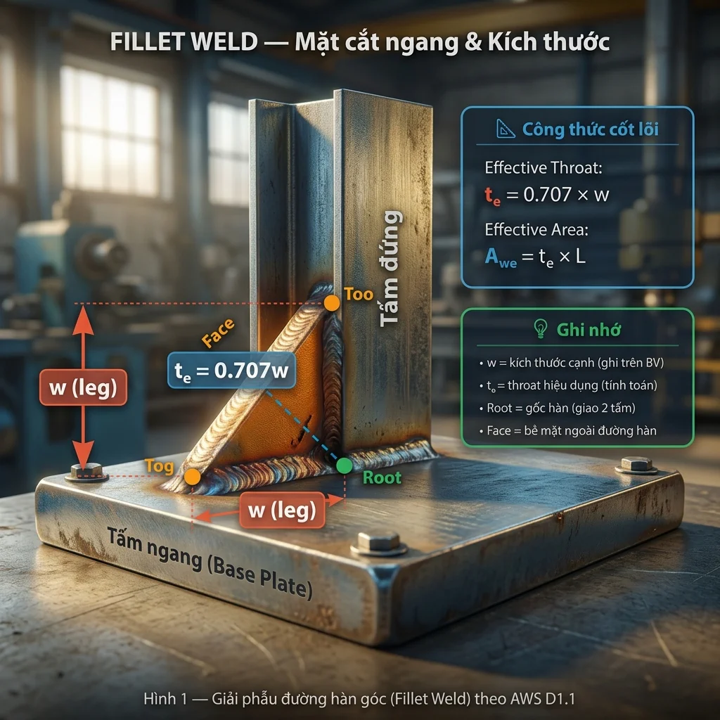
Effective throat  te  = 0.707 × leg size (w)
Effective area    Awe = te × effective length (L)
Figure 1. Fillet weld anatomy — leg size versus effective throat.
2.2 Groove weld
Joins two members in the same plane (butt joint) and requires edge preparation.
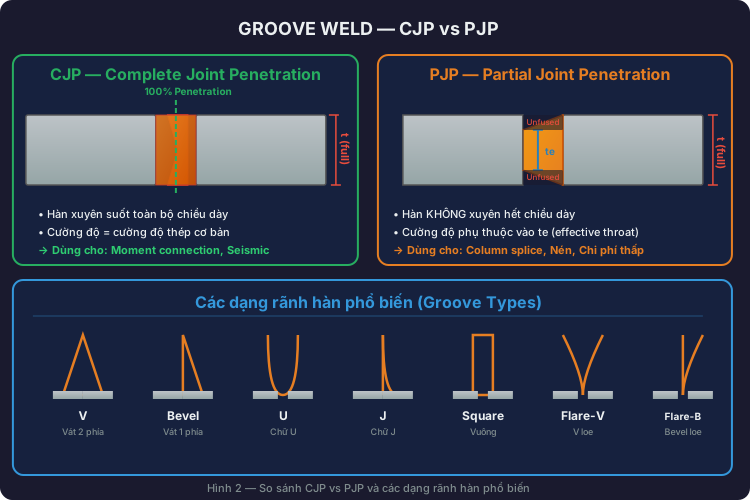
CJP — complete joint penetration: weld metal penetrates the full thickness. Used for moment connections, column splices and seismic detailing. Design strength = base metal strength → no separate weld check with matching filler metal.
PJP — partial joint penetration: weld metal does not penetrate the full thickness. Effective depth depends on groove angle, process and position. Used for compression connections and non-critical joints.
Symbol
Groove type
Notes
V
V-groove
Both sides beveled, most common
Bevel
Single bevel
One plate beveled, the other square
U
U-groove
Reduces weld volume for thick plates
J
J-groove
Similar to U, single side
Square
Square
No preparation, thin plates only
Flare-V
Flare-V
For round or curved sections
Flare-Bevel
Flare-bevel
One curved and one flat surface
Figure 2. CJP versus PJP, and the common groove types.
2.3 Plug and slot welds
Plug weld: welding through a circular hole in the cover plate to the plate below.
Slot weld: the same concept with a rectangular, elongated hole.
Their purpose is shear transfer and preventing separation — they are not used for direct tension.
3. Welding symbols per AWS A2.4
Term
Meaning
Weld Symbol
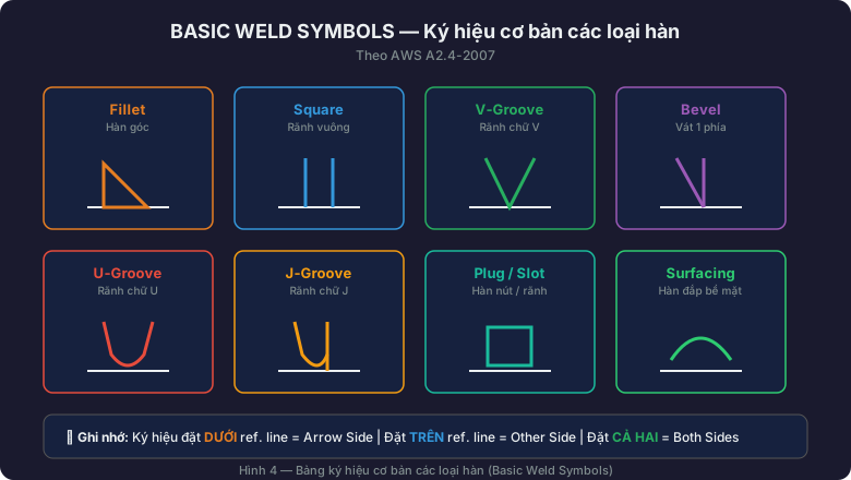
The small graphic showing the weld type (triangle = fillet, V = groove…)
Welding Symbol
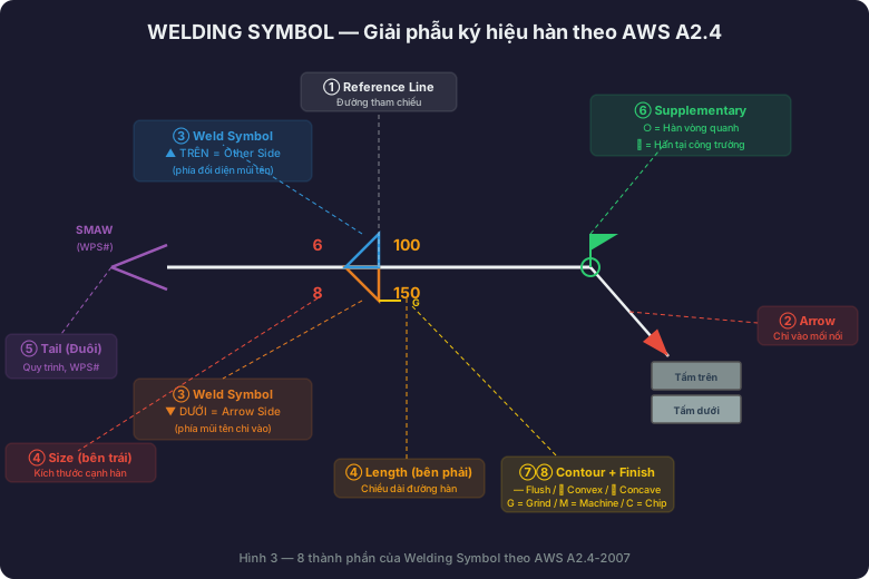
The complete symbol: reference line, arrow, weld symbol, dimensions, tail and supplementary symbols
Figure 3. Basic weld symbols chart.
The eight components of a welding symbol
Reference line — the foundation; all information sits above or below it.
Arrow — points to the joint to be welded.
Weld symbol — the graphic for the weld type.
Dimensions — size on the left, length and pitch on the right.
Tail — process (SMAW, GMAW…) or WPS number.
Supplementary symbols — contour and finish.
Finish symbol — G = grinding, M = machining, C = chipping.
Contour symbol — flush, convex or concave.
Figure 4. The eight components of a welding symbol per AWS A2.4-2007.
The Arrow Side / Other Side rule
Arrow side — the side the arrow points to → symbol placed BELOW the reference line.
Other side — the side opposite the arrow → symbol placed ABOVE the reference line.
Both sides — symbols placed above and below.
Symbol
Name
Meaning
○ at the intersection
Weld-all-around
Weld the entire perimeter
⚑ (flag)
Field weld
Welded on site, not in the shop
▬ (rectangle)
Backing
A backing bar is used behind the weld
◑ (half-filled circle)
Melt-through
The weld must penetrate and be visible from the back
─── (dash)
Spacer
A spacer plate between the members
4. Size requirements per AISC 360 & AWS D1.1
Minimum fillet weld size
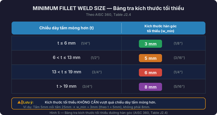
Per AISC 360, Table J2.4 — based on the thinner plate:
Thinner plate thickness (t)
Minimum fillet size
t ≤ 6 mm (1/4")
3 mm (1/8")
6 < t ≤ 13 mm (1/2")
5 mm (3/16")
13 < t ≤ 19 mm (3/4")
6 mm (1/4")
t > 19 mm (3/4")
8 mm (5/16")
Figure 5. Minimum fillet weld size lookup table.
Maximum size and effective length
Maximum size: plate < 6 mm → equal to the plate thickness; plate ≥ 6 mm → thickness minus 2 mm. The reason is to avoid melting or notching the plate edge.
Minimum length: ≥ 4 × leg size (4w) and not less than 38 mm.
Intermittent welds: each segment ≥ 4w, and the pitch must be noted on the drawing.
Return/boxing: required for lap joints in tension — wrap around the end ≥ 2w.
Effective throat for PJP groove welds
The effective depth of a PJP weld depends on the groove angle, the welding process and the welding position.
Groove angle (θ)
Effective throat
θ ≥ 60°
Groove depth (D)
45° ≤ θ < 60° (SMAW/GMAW)
D − 3 mm (1/8")
θ < 45°
Must be qualified by PQR
5. Weld type selection guide
Design scenario
Recommended weld
Beam–column (moment connection)
CJP groove at the flanges, fillet at the web
Gusset plate to beam or column
Fillet weld
Column splice — compression
PJP groove weld
Column splice — seismic zone
CJP groove weld
Stiffener
Fillet weld
Base plate
Fillet weld or PJP
HSS tube connection
CJP or PJP depending on the load
Preventing delamination in a lap
Plug or slot weld
Pre-issue drawing checklist
Weld type specified (fillet / groove / plug)?
Size noted (leg size or groove depth)?
Length indicated — continuous or intermittent?
Symbol placed on the correct arrow side / other side?
Size ≥ the minimum and ≤ the maximum?
CJP or PJP specified for groove welds?
Shop weld or field weld clearly identified?
Does the tail carry the WPS or special process note?
Reviewed with the fabrication and erection team before release?
Part 1 summary
Content
Keyword
Fillet weld is the most common; throat = 0.707 × leg
te = 0.707w
CJP develops full strength, PJP only partial
CJP vs PJP
Below the reference line is arrow side, above is other side
Arrow / Other
Minimum size follows the thinner plate (Table J2.4)
Min Size
Maximum size = thickness − 2 mm (plate ≥ 6 mm)
Max Size
Minimum length ≥ 4w and ≥ 38 mm
Min Length
Weld symbol ≠ welding symbol
Symbol ≠ Full Symbol
Always run the checklist before issuing drawings
QA / QC
Part of the series "Structural design for industrial facilities" — Roberto Structural. The content is technical guidance; the engineer remains responsible for checking and adapting it to the conditions of each project and the requirements of the governing code. Standards evolve — always check the latest editions of AWS D1.1, AISC 360 and AWS A2.4 before applying them.
 Roberto