Concrete Slab on Grade — A Structural Engineer's Design Handbook
Structural Notes · No. 06·07 Aug 2026·20 min read
1. What is a concrete slab on grade?
A concrete slab placed directly on the ground (subgrade / subbase).
Not a structural element of the building — it is non-structural per ACI 360.
Its purpose is to provide a flat surface carrying operational loads such as forklifts, racks and partition walls.
Design focuses on serviceability: crack control, curling and flatness.
2. The Winkler subgrade model
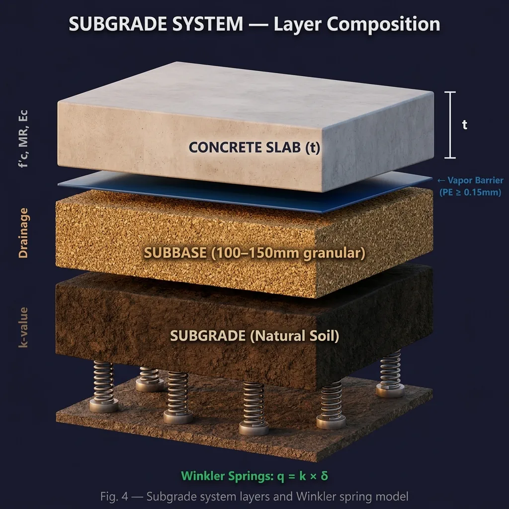
The subgrade is modelled as a system of independent springs (dense liquid foundation).
Each point reacts linearly with settlement: q = k × δ.
The model is simple yet accurate enough for practical design.
Modulus of subgrade reaction, k
k is the pressure required to cause one unit of deformation, in pci (lb/in³) or MN/m³. It is measured by a field plate load test (Ø750 mm plate) or estimated from a CBR correlation. Remember that k is not a constant — it depends on soil type, moisture content and plate size.
Soil type (USCS)
k (pci)
k (MN/m³)
Notes
Organic soils (OL, OH, Pt)
25–100
7–27
Very weak, improvement needed
High-plasticity clays/silts (CH, MH)
50–150
14–41
Moisture-sensitive, k varies widely
Low-plasticity clays/silts (CL, ML)
50–200
14–54
Most common
Silty/clayey sands (SM, SC)
50–250
14–68
—
Sands (SW, SP)
150–400
41–109
Good
Silty/clayey gravels (GC, GM)
200–500
54–136
—
Gravels (GW, GP)
300–500
82–136
Very good
3. Radius of relative stiffness — the key parameter
Lr = ⁴√[ E·t³ / ( 12·k·(1 − μ²) ) ]
Symbol
Meaning
Unit
Lr
Radius of relative stiffness
mm (in)
E
Concrete modulus of elasticity
MPa (psi)
t
Slab thickness
mm (in)
k
Modulus of subgrade reaction
MN/m³ (pci)
μ
Poisson's ratio (≈ 0.15–0.20)
—
Lr represents the zone of influence of a load on the slab. A large Lr means the slab is stiff relative to the subgrade, the load spreads further and stresses are lower. A small Lr means the slab is flexible relative to the subgrade, the load concentrates and stresses are higher.
4. Westergaard theory — three loading positions
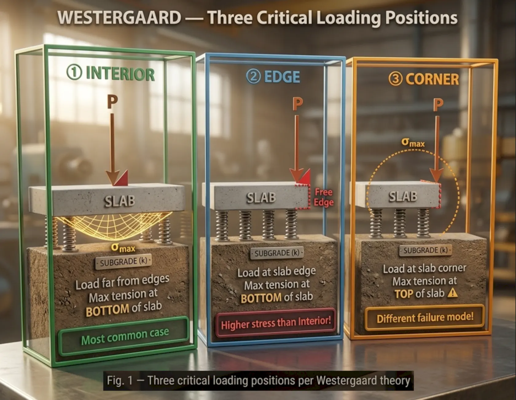
Figure 1. Westergaard's three loading positions: interior, edge and corner.
Interior loading
The load sits far from any edge or corner.
Maximum tensile stress is at the bottom of the slab, directly under the load.
This is the most common case in industrial buildings — forklifts and rack posts.
fb = [ 3P(1+μ) / (2π·t²) ] × [ ln(2Lr/b) + 0.5 − γ ]

P = concentrated load      γ ≈ 0.5772 (Euler's constant)
b = equivalent radius of the resisting section
  when a < 1.724t :  b = √(1.6a² + t²) − 0.675t
  when a ≥ 1.724t :  b = a
Edge and corner loading
Edge loading: on the slab edge but away from corners. Tensile stress is higher than interior loading because support is lost on one side — check it separately.
Corner loading: the maximum tensile stress is at the top of the slab — the opposite of the other two cases.
This is an allowable stress approach: compute the applied stress and compare it with the allowable stress, which is the modulus of rupture divided by a factor of safety.
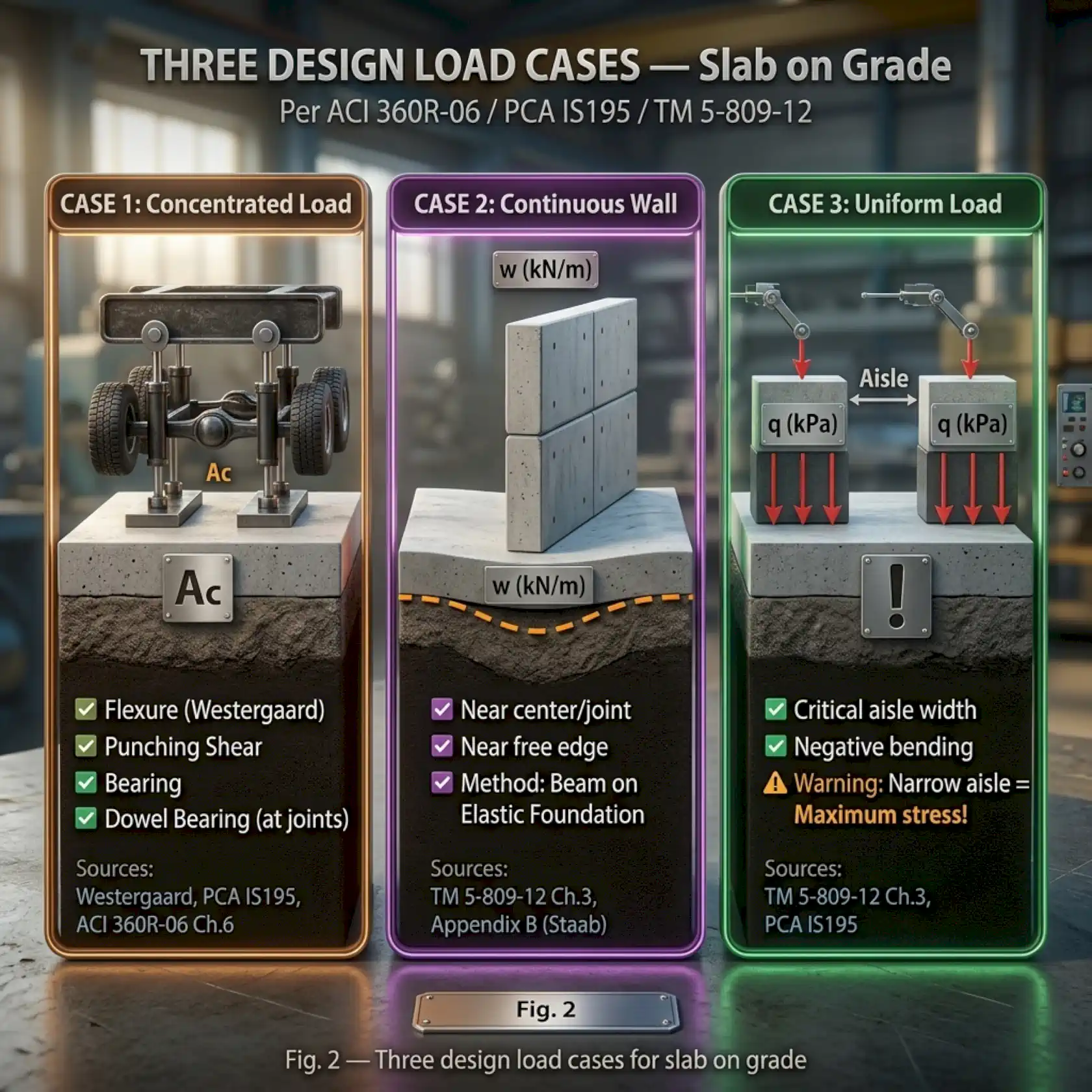
Checks: Westergaard flexure, punching shear, bearing, and dowel bearing if near a joint.
Inputs: P, contact area Ac, f'c, t, k and FoS — where Ac = P / p, with p the tyre or post pressure.
Case 2 — continuous wall load
The load comes from masonry or partition walls built on the slab. It is analysed as a beam on elastic foundation per TM 5-809-12, checked at two positions: near the centre (or a joint) and near a free edge.
Case 3 — uniform load
The load comes from stacked goods or stored materials. The critical condition is the aisle width between loaded areas: the maximum stress occurs when the aisle is narrow, where the slab bends in the opposite direction.
Punching shear and finding the minimum thickness
fv = P / (b₀ × t)

b₀ = perimeter of the critical section, taken at d/2 from the load edge
Allowable stress  Fv = 4√f'c (psi)  or  0.33√f'c (MPa)
Assume a trial thickness t.
Compute Lr, fb and fv for each load case.
Check fb ≤ MR/FoS and fv ≤ the allowable Fv.
If a check fails, increase t and repeat; t_min is the smallest thickness at which every check passes.
6. Joint design
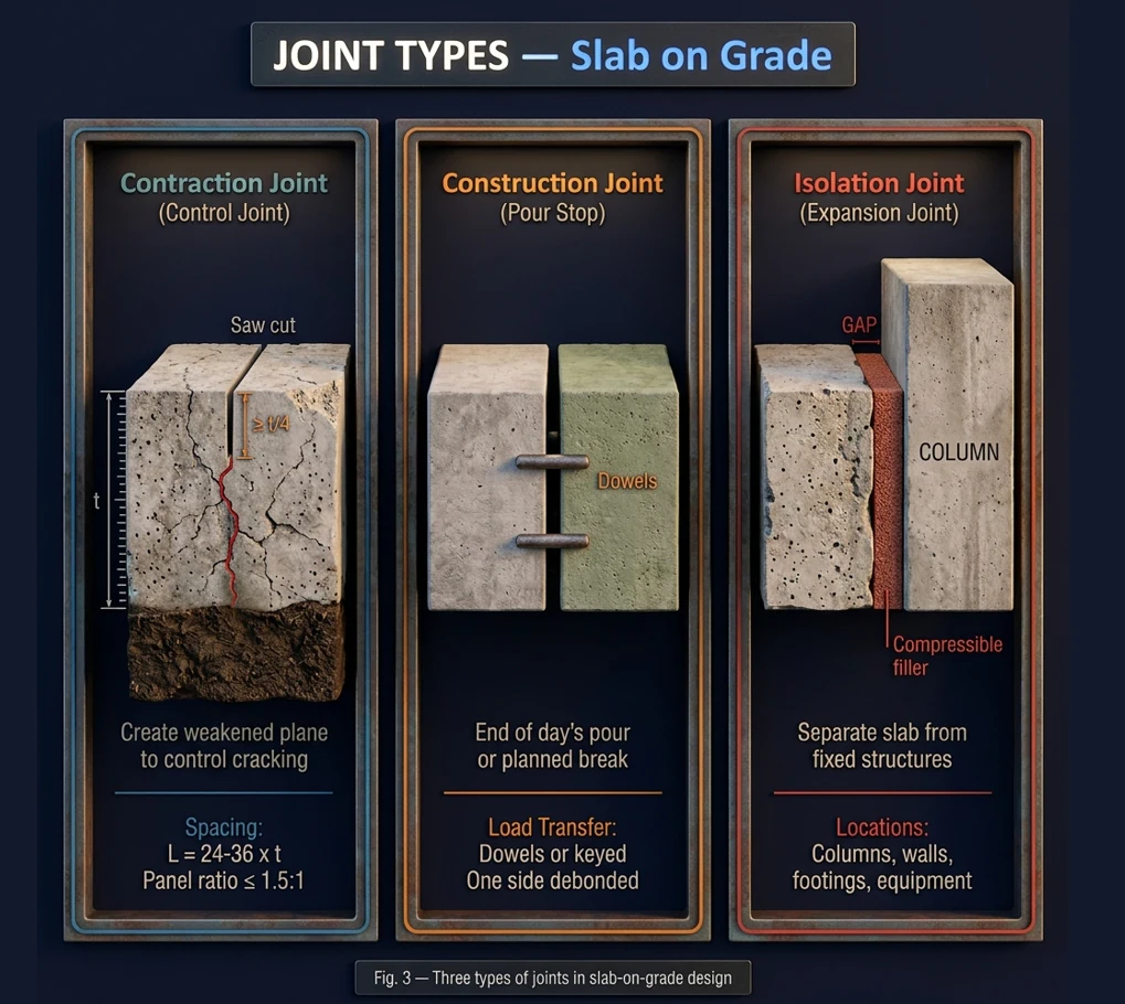
Figure 3. Joint types in a slab on grade.
Joint type
Purpose
Location
Contraction joint
Creates a weakened plane to control cracking
Saw cut 1/4–1/3 of the slab depth
Construction joint
Boundary of a day's concrete pour
End of the pour or a planned break
Isolation joint
Separates the slab from fixed structures
Around columns, walls and equipment bases
Joint spacing
Rule of thumb: L = (24 to 36) × slab thickness. A 150 mm slab gives L = 3.6–5.4 m; a 200 mm slab gives L = 4.8–7.2 m.
Prefer square panels; if rectangular, keep the length-to-width ratio below 1.5.
Align joints with the column grid where possible.
Dowel bars
Purpose: transfer vertical load across the joint and prevent faulting between panels.
Use a smooth round bar; one half must be debonded so the joint can open and close.
The diameter is typically ≈ t/8 (about 20–25 mm for a 150–200 mm slab).
Length 400–500 mm with 200–250 mm projecting each side; spacing 300 mm.
Reinforcement becomes necessary when joint spacing is large, when crack width must be controlled, or when the temperature differential is significant.
Shrinkage and temperature reinforcement
As = ( f × L × W × t × γ ) / ( 2 × fs )
Symbol
Meaning
f
Slab-to-subgrade friction coefficient (1.0–2.5, typically ≈ 1.5)
L
Distance between joints
W
Concrete unit weight (≈ 2400 kg/m³)
t
Slab thickness
γ
Factor, equal to 1 for a single layer at mid-depth
fs
Allowable steel stress (typically 0.67fy)
Crack-control reinforcement is placed in the upper third of the slab depth.
Do not run deformed bars through a contraction joint — it stops the joint working and moves the crack elsewhere.
Crack width is estimated as w = ε × L_joint / 2, where ε combines drying shrinkage and thermal contraction.
8. Subgrade preparation and curling
Figure 4. The layer system beneath a concrete slab on grade.
Subgrade: must be compacted and uniform; remove weak and organic soils.
Subbase: 100–150 mm of sand or crushed stone to spread load, drain water and provide a working platform.
Vapour barrier: a PE film ≥ 0.15 mm beneath the slab to stop moisture rising from the ground.
Slip membrane: reduces slab-to-subgrade friction and therefore shrinkage stress.
Curling and how to reduce it
Slab edges curl upward because of moisture and temperature gradients between top and bottom: the top dries and shrinks faster while the underside stays damp. The slab then loses contact with the subgrade at edges and corners, load concentrates there and cracking follows.
Reduce the water–cement ratio to reduce shrinkage.
Use the largest practical aggregate size to reduce water demand.
Cure properly for at least seven days to reduce the moisture gradient.
Keep joint spacing sensible so panels stay small.
Provide top reinforcement to control curling cracks.
Environmental conditions considered: temperature differential, moisture?
Design phase
f'c selected and MR, Ec calculated?
k-value determined by test or lookup table?
Radius of relative stiffness Lr calculated?
Flexure checked for all three load cases?
Punching shear and bearing checked?
Minimum thickness t_min determined?
Joints designed: location, spacing, type?
Dowel bars designed where needed?
Shrinkage/temperature reinforcement calculated and crack width checked?
Construction phase
Subgrade compacted and uniform?
Subbase placed to the correct thickness?
Vapour barrier installed?
Reinforcement or mesh placed correctly in the upper third?
Dowels placed correctly and debonded on one side?
Concrete placed at the correct slump and grade?
Contraction joints cut at the right time (4–12 hours after placement)?
Cured for at least seven days?
11. Related standards
Standard
Scope
What engineers need to know
ACI 360R
Slab on grade design
The primary reference — methods, formulas and detailing
ACI 318
Structural concrete design
Applies only when the slab is a structural element
ACI 302.1R
Concrete floor construction
Construction, curing and flatness requirements
PCA IS195
Industrial floor thickness design
PCA design charts and tables
TM 5-809-12
Heavy-load concrete floor slabs
Wall load, uniform load and lookup tables
Westergaard (1926)
Elastic plate on elastic foundation
The original equations for interior, edge and corner loading
Supporting design tools
Closing — ten things to remember
Content
Keyword
The subgrade is a Winkler spring system, q = k × δ
Winkler k
Lr is the key parameter behind every formula
Lr
Three loading positions: interior, edge, corner
3 Positions
Interior loading usually governs
Interior Governs
Working stress is MR divided by a factor of 1.7–2.0
Working Stress
MR = 9√f'c (psi) or 0.75√f'c (MPa)
MR
Joints at 24–36 times the thickness, square panels
Joint Spacing
Dowels must be round, smooth and debonded on one side
Dowel Bar
Reinforcement does not prevent cracks, it only keeps them tight
Crack Control
A uniform subgrade makes a good slab — investing there always pays
Subgrade First
Part of the series "Structural design for industrial facilities" — Roberto Structural. The content is technical guidance; the engineer remains responsible for checking and adapting it to the conditions of each project and the requirements of the governing code.
 Roberto