 Roberto
1. Overview — what makes pipe racks special?
- A pipe rack is a steel framing system that supports process piping, cable trays and instrument trays in industrial plants (oil & gas, petrochemical, power).
- Not a building — it is a non-building structure with unique load characteristics.
- Thermal/friction loads from piping expansion — often the governing lateral load.
- Highly variable loads — pipes can be empty, full, or under test pressure.
- Multi-discipline coordination — structural, piping, electrical and instrument teams must align.
- Modular construction — bolted connections preferred for field erection.
- Future expansion — consider designing with 10–25% additional capacity.
2. Structural configuration
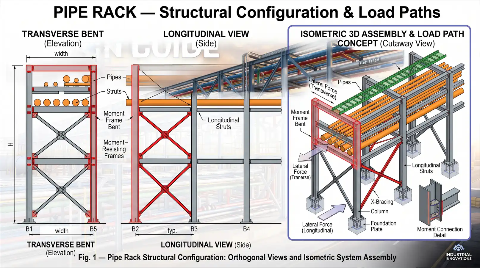
2.1. Transverse direction — moment frame
- Each moment frame is a rigid (portal) frame of 2 columns + one or more beams.
- Resists transverse lateral loads (wind, seismic perpendicular to the pipe run).
- Column bases: typically fixed or pinned, depending on the design strategy.
- Beam-to-column connections: rigid (moment-resisting).
- Must remain open below for access, maintenance and equipment clearance.
2.2. Longitudinal direction — braced frame
- Vertical bracing (X-bracing or inverted V) placed at intervals along the rack.
- Column bases: usually pinned.
- Longitudinal struts connect bents at beam level to transfer lateral loads to the braced bays.
- Resists friction loads, wind and seismic parallel to the pipe run.
3. Loading — the most critical step
3.1. Dead load (D)
- Piping weight: empty weight + insulation weight.
- Cable tray weight: tray + cables (typically 20–150 kg/m per tray).
- Self-weight: steel members, fireproofing (if any).
- Preliminary design load if pipe data is not yet available: piping level 10–15 kPa (200–300 psf) per level; cable tray level 2.5–5 kPa (50–100 psf).
3.2. Live load (L)
- Platform: 2.5–5.0 kPa (50–100 psf).
- Construction/erection loads: per project specification.
3.3. Operating load (Do)
Dead load + fluid content weight under normal operation. This is the primary gravity load for most design checks.
3.4. Test load (Dt)
- Dead load + hydrotest water weight (water is heavier than most process fluids).
- Applied one pipe at a time — not all pipes simultaneously.
- Can be the governing gravity load for large-diameter pipes.
3.5. Thermal / friction load (Ff)
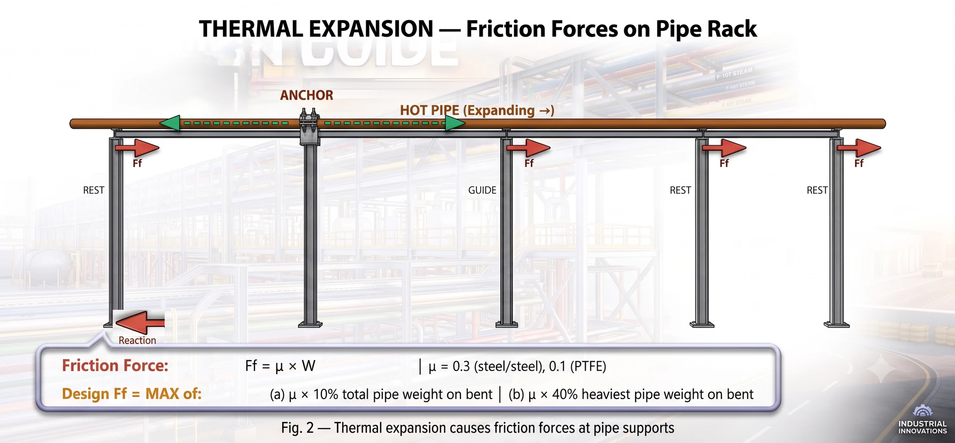
This is the signature load of pipe rack design — absent in conventional buildings.
- Cause: pipes expand/contract with temperature → slide on supports → friction force.
- Direction: primarily longitudinal (along the pipe run).
- Friction coefficient (μ): steel-on-steel ≈ 0.3; steel-on-PTFE ≈ 0.05–0.10.
Ff = MAX of:
  (a) μ × 10% of total piping weight on the bent
(b) μ × 40% of the heaviest single pipe weight on the bent- Anchor loads: where pipes are anchored, the full thermal expansion force is transferred directly — this can be very large (hundreds of kN).
- Guide loads: lateral forces at guide locations — the pipe can move axially but is restrained laterally.
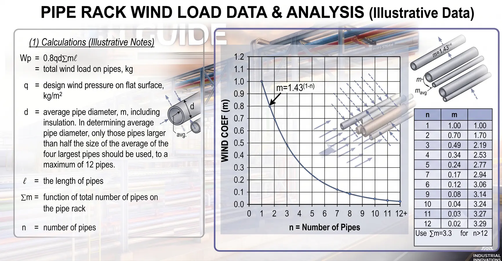
3.6. Wind load (W)
- Calculated per ASCE 7 (or the local code).
- Applied on the projected area of columns, beams, pipes, cable trays and insulation.
- Pipe area: use the total projected diameter (including insulation).
- Shielding effect: some codes allow a reduction for multiple pipe rows.
- Wind on a pipe rack is typically transverse (perpendicular to the pipe run).
3.7. Seismic load (E)
- Per ASCE 7 and the project seismic parameters.
- For non-building structures: use the specific R-factors and importance factors.
- Typical pipe rack values: R = 3.5-8.0 for ordinary moment frames (transverse); R = 8 for ordinary braced frames (longitudinal). Higher values may apply to special or intermediate frames.
- Seismic weight includes the structure weight + the operating piping weight.
3.8. Load summary table
| Load | Symbol | Direction | Notes |
|---|---|---|---|
| Dead | D | Vertical ↓ | Structure + empty pipe + insulation |
| Operating | Do | Vertical ↓ | D + fluid content |
| Test | Dt | Vertical ↓ | D + hydrotest water (one pipe at a time) |
| Live | L | Vertical ↓ | Platform |
| Friction | Ff | Longitudinal ← → | Thermal pipe expansion |
| Anchor | Fa | Longitudinal / lateral | Piping stress analysis |
| Wind | W | Transverse / longitudinal | ASCE 7, on projected area |
| Seismic | E | Both directions | ASCE 7, operating weight |
4. Load combinations — AISC 360 / ASCE 7
4.1. LRFD load combinations (primary)
1)  1.4D
2)  1.2D  + 1.6L
3)  1.2Do + 1.0L + 1.6W
4)  1.2Do + 1.0E
5)  0.9D  + 1.6W      (uplift / overturning check)
6)  0.9D  + 1.0E      (uplift / overturning check)
7)  1.2D  + 1.6Ff     (friction as the primary lateral load)
8)  1.2Dt             (hydrotest — special case)
4.2. Key notes on combinations
- Friction (Ff) is a separate lateral load — not combined with wind or seismic simultaneously (they do not occur together).
- Test load (Dt) is a special condition — combined only with dead load; no live, wind or seismic.
- Always check both uplift (0.9D + W or E) and maximum gravity (1.2Do + 1.6L).
- Use notional loads if using the Direct Analysis Method.
5. Analysis approach
5.1. Separated analysis (recommended for standard racks)
Most pipe racks can be efficiently analysed by separating the two orthogonal directions:
- ① Transverse moment frame (2D): portal frame with 2 columns + beams; gravity + transverse wind/seismic; output is column sizes, beam sizes and interaction ratios.
- ② Longitudinal braced bay (2D truss): braced frame with struts + bracing + tributary columns; friction + longitudinal wind/seismic; output is bracing sizes, strut sizes and the longitudinal column check.
- ③ Combine results: the governing column ratio = MAX (transverse check, longitudinal check, biaxial interaction).
5.2. Full 3D analysis (for complex racks)
- Non-uniform geometry (varying heights, offsets).
- Heavy equipment mounted on the rack.
- Large anchor loads from piping stress analysis.
- Seismic design requiring modal or response spectrum analysis.
5.3. Second-order effects (P-Δ)
- AISC 360 requires consideration of second-order effects.
- Direct Analysis Method (DAM): preferred — apply notional loads, use reduced stiffness, K = 1.0.
- Effective Length Method (ELM): calculate the K-factor for sway frames.
- For most pipe racks of moderate height, the B₂ amplifier is typically 1.05–1.15.
6. Beam design
6.1. Loading on beams
- Beams support pipes at discrete points, not as a uniform load.
- Each pipe support is a point load on the beam.
- For cable trays: treat as a uniform distributed load (UDL).
- Beam self-weight: include as a UDL.
6.2. Design checks
| Check | Formula / reference | Notes |
|---|---|---|
| Flexure | Mn = Mp = Fy × Zx (compact) | AISC 360 Chapter F |
| Shear | Vn = 0.6Fy × Aw × Cv | AISC 360 Chapter G |
| Deflection | δ ≤ L/240 (DL+LL) or L/360 (LL) | Serviceability |
| Lateral-torsional buckling (LTB) | Check Lb against Lp, Lr | Unbraced length is critical |
| Web local buckling | h/tw limit | Compact section preferred |
6.3. Unbraced length (Lb) for beams
- Top flange in compression: Lb = the distance between lateral braces.
- Bottom flange in compression (negative moment at connections): Lb = the full beam span unless specifically braced.
7. Column design — beam-column interaction
This is the most critical member design in a pipe rack.
7.1. Steel column design
- Axial compression (gravity from all levels).
- Bending about the strong axis (transverse lateral loads — moment frame action).
- Bending about the weak axis (longitudinal friction/wind — if unbraced longitudinally).
- → Must satisfy the AISC 360 Chapter H interaction equations.
7.2. AISC H1-1 interaction equations
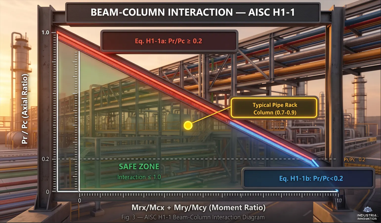
When Pr/Pc ≥ 0.2:
  Pr/Pc + (8/9)(Mrx/Mcx + Mry/Mcy) ≤ 1.0    — Eq. H1-1a

When Pr/Pc < 0.2:
Pr/(2Pc) + (Mrx/Mcx + Mry/Mcy) ≤ 1.0 — Eq. H1-1b| Symbol | Meaning |
|---|---|
| Pr | Required axial strength (factored) |
| Pc | Available axial strength (φPn) |
| Mrx, Mry | Required flexural strength (strong, weak axis) |
| Mcx, Mcy | Available flexural strength (φMn) |
7.3. Critical unbraced lengths for columns
| Direction | Major axis | Minor axis |
|---|---|---|
| Transverse | Base to beam (moment frame) | Base to first strut or beam |
| Longitudinal | Base to beam | Base to first strut or beam |
| K-factor (DAM) | K = 1.0 | K = 1.0 |
| K-factor (ELM, sway) | K > 1.0 (alignment chart) | K > 1.0 (if unbraced) |
7.4. Step-by-step column design
- 1. Determine loads: Pr, Mrx, Mry from the analysis (including second-order effects).
- 2. Select a trial section: H-shape with the strong axis oriented transversely.
- 3. Calculate Pc: based on KLx/rx and KLy/ry — use the smaller Pn.
- 4. Calculate Mcx: based on Lb (the unbraced length for LTB).
- 5. Calculate Mcy: the weak-axis bending capacity.
- 6. Check H1-1a or H1-1b: interaction ratio ≤ 1.0.
- 7. Iterate if the ratio is > 1.0 or < 0.6 (optimise).
Part 1 summary
| # | Content | Keyword |
|---|---|---|
| 1 | Pipe rack = non-building structure, lateral loads often govern | Non-Building |
| 2 | Transverse = moment frame, longitudinal = braced frame | Two Systems |
| 3 | Thermal friction is THE signature load of pipe racks | Ff = μ × W |
| 4 | Friction and wind/seismic are NOT combined simultaneously | Exclusive Lateral |
| 5 | Pipe supports may NOT brace the beam | Lb Caution |
| 6 | Column = beam-column, check AISC H1-1 interaction | Interaction |
| 7 | Weak-axis unbraced length often controls | Weak Axis KL/r |
Part of the series “Structural design for industrial facilities” — Roberto Structural. The content is technical guidance; the engineer remains responsible for checking and adapting it to the conditions of each project and the requirements of the governing code.
Share this article