 Roberto
1. Why second-order analysis rather than moment magnification?
ACI 318-14 opens three routes for handling second-order effects:
| Route | Clause | Method | Suited to |
|---|---|---|---|
| 1 | §6.6.4 | First-order analysis + moment magnification δns, δs | Regular framed buildings, simple geometry |
| 2 | §6.7 | Second-order elastic analysis | Industrial structures, irregular framing |
| 3 | §6.8 | Material nonlinear analysis | Assessment, retrofit, research |
For plant structures — equipment support frames, local access platforms, staggered levels, long columns with no tie beams, column bases on pile caps — Route 1 is ruled out by its own definition. The stability index Q, the sums ΣPu and ΣPc, and the length lu in §6.6.4.4.3 all rest on a notion of “a storey” that such structures barely possess.
Route 2 shifts the burden onto the model. In return, the engineer must comply with four conditions:
- Section stiffness must be reduced per §6.6.3.1.1 (referenced again in §6.7.2.1.1);
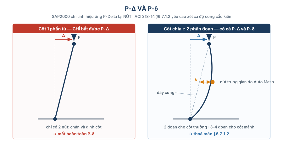
- The analysis must capture both P-Δ (joint displacement) and P-δ (curvature within the member) — §6.7.1.2;
- The design side must set δns = δs = 1.0, otherwise second-order effects are counted twice;
- M2nd ≤ 1.4 × M1st — §6.2.6.
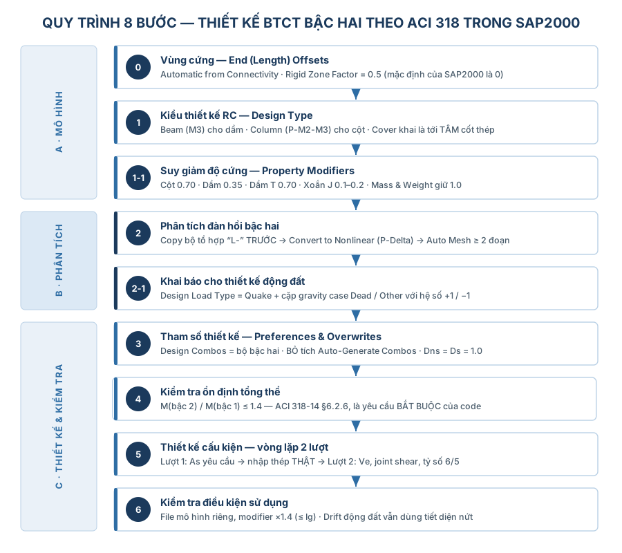
2. Step 0 — Rigid zones (end offsets)
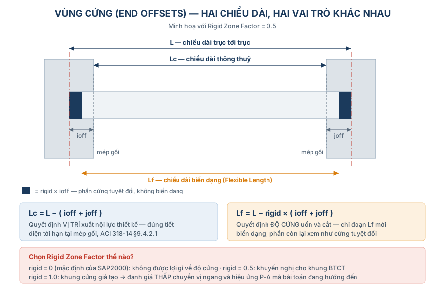
Assign > Frame > End (Length) Offsets…Frame elements in SAP2000 join mathematical nodes, but real beams and columns have width — the intersection zone is counted twice unless offsets are declared.
- Lc = L − (ioff + joff) → clear length. It fixes where design forces are reported, matching the critical-section-at-face-of-support requirement of ACI 318-14 §9.4.2.1.
- Lf = L − rigid × (ioff + joff) → deformation length. It fixes the member's flexural and shear stiffness.
Rigid Zone Factorruns from 0 to 1.0. SAP2000 defaults to 0 — you get the benefit in design location but none in stiffness.
Practical recommendations
- Choose
Automatic from Connectivityso SAP computes ioff/joff from the real sections. - Use rigid = 0.5 for ordinary RC frames. An RC joint is not perfectly rigid: it deforms in shear within the joint region.
- Do not use rigid = 1.0. It makes the frame artificially stiff → underestimates lateral drift → and therefore underestimates the very P-Δ effect.
3. Step 1 — Choosing the RC design type
Define > Section Properties > Frame Sections > Concrete Reinforcement…| Type | Meaning | Use for |
|---|---|---|
Beam (M3 Design Only) | Flexure about axis 3 only, axial force ignored | Beams in pure flexure |
Column (P-M2-M3 Design) | Design on the P-M2-M3 interaction surface | Columns and members with significant axial load |
Three easy mistakes
Concrete Coverin the dialog is the distance to the centroid of the reinforcement (to the tie for columns, to the longitudinal bar for beams) — not the clear cover.- For columns, the first run uses
Reinforcement to be Designedso SAP computes the required As. The later run switches toReinforcement to be Checkedwith the actual bar layout (see Step 5). - Collector beams, tie beams and transfer beams in a seismic system carry large axial force. Leaving them as
Beammakes SAP discard P entirely → unsafe. Declare them asColumn, or check them by hand.
4. Step 1-1 — Stiffness reduction (property modifiers)
Set Modifiers… in the section dialog, or Assign > Frame > Property Modifiers.
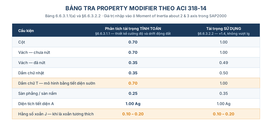
Quick lookup — ACI 318-14 Table 6.6.3.1.1(a) and §6.6.3.2.2
| Member | Factored-load analysis (§6.6.3.1.1) | Service-load analysis (§6.6.3.2.2 — ×1.4, not exceeding Ig) |
|---|---|---|
| Column | 0.70 Ig | 1.00 Ig |
| Uncracked wall | 0.70 Ig | 1.00 Ig |
| Cracked wall | 0.35 Ig | 0.49 Ig |
| Rectangular beam | 0.35 Ig | 0.49 ≈ 0.50 Ig |
| T-beam (modelled as the web section) | 0.70 Ig,web | 1.00 Ig,web |
| Flat plate / flat slab | 0.25 Ig | 0.35 Ig |
| Section area A | 1.0 Ag | 1.0 Ag |
| Torsional constant J | see the note below | see the note below |
Why is a T-beam 0.70 and not 0.35?
R6.6.3.1.1 permits Ig of a T-beam to be taken as twice the Ig of the web, i.e. 2·(bwh³/12). When you model a rectangular bw×h section in SAP2000, the factor to enter is 0.35 × 2 = 0.70.
- If you have already modelled a true T-section (or a beam acting compositely with a shell slab), do not double it again — the flange is already in Ig.
The torsional constant J — what the manuals leave out
Leaving J = 1.0 models the beam with uncracked torsional stiffness. In a real RC frame, spandrel beams crack in torsion very early and shed the torsional moment. Keeping J = 1.0 draws a fictitious torsion into the spandrel, leading to stirrups and longitudinal torsion bars that are not needed.
- Recommendation: J modifier = 0.1 to 0.2 where the torsion is compatibility torsion (ACI 318-14 §22.7.3).
- Keep J = 1.0 where the torsion is equilibrium torsion — a cantilever beam carrying a slab on one side, or a beam supporting an overhanging roof.
Two notes on modifiers in SAP2000
- A modifier set at section level and one assigned at object level multiply together. Entering 0.35 in both places gives 0.1225 — a model three times more flexible than intended. Use one place only.
- The
MassandWeightfields (green background) stay at 1.0. Reducing them reduces the self weight as well.
5. Step 2 — Setting up the second-order elastic analysis
SAP2000 computes P-Delta only inside a nonlinear static load case. And nonlinear problems do not superpose. The consequence: every factored load combination must become its own load case, carrying that combination's own factors.
The mandatory order — get it wrong and you lose data
- 1. Select the design combinations (strength): erection, operating and test combinations per the project spec.
- 2. Copy the whole set into a second set prefixed
L-(e.g.L-LC1001). This set stays first-order, for the comparison in Step 4. - 3.
Define > Load Combinations > Convert Combos to Nonlinear Cases…→ SAP createsLC1001-NLand rewritesLC1001as aLinear Addcombination containing onlyLC1001-NLat factor 1.0. - 4. Spot-check a few converted cases (
Define > Load Cases > Modify/Show) against the table below.
| Field | Correct value |
|---|---|
Load Case Type / Analysis Type | Static / Nonlinear |
Geometric Nonlinearity | P-Delta — not P-Delta plus Large Displacements (slow, prone to divergence, unnecessary for building frames) |
Initial Conditions | Zero Initial Conditions |
| Load pattern & scale factor | exactly the combination factors |
Results Saved | Final State Only (a large file-size saving once there are more than 100 cases) |
Subdivide members to capture P-δ
Assign > Frame > Automatic Frame Mesh…
  Auto Mesh Frame
  at Intermediate Joints
Minimum Number of Segments = 2- P-Delta in SAP2000 is evaluated at nodes only. A single-element column gives P-Δ alone, no P-δ → a breach of §6.7.1.2.
- Use 2 segments for ordinary columns, 3–4 segments for slender columns (klu/r > 60) or columns supporting heavy equipment.
Automatic Frame Meshis the right tool. Auto mesh subdivides the analysis element only; the design object stays intact.
Output stations
Assign > Frame > Output Stations…
  Minimum Number of Stations = 9
  ☑ At Intersections with Other Elements
  ☑ At Concentrated Load Locations
Beams need many stations (the peak force sits mid-span). Columns only need their two ends — 3–5 stations per column is enough and shortens the run.
6. Step 2-1 — Load case type and dead load case for seismic design
This is the subtlest step, and the one most often skipped.
After conversion SAP2000 no longer knows which combination contains seismic load, nor which part of it is gravity. Both facts are vital to Chapter 18.
(a) Letting SAP recognise the seismic load
Load Case Data > Load Case Type > Design…
  User Defined = Quake        (for every nonlinear case containing seismic load)
Only when it sees the Quake label does SAP2000 activate the ACI 318-14 Chapter 18 provisions: design shear from Mpr, joint shear check, the 6/5 ratio, and the minimum reinforcement limits at both beam ends.
(b) Letting SAP recognise the gravity load — the Dead/Balance pair trick
ACI 318-14 §18.6.5.1 defines the design shear of a beam:
Ve = (Mpr1 + Mpr2) / ln ± wu · ln / 2SAP2000 can compute the Mpr part, but it needs to know wu. The method:
- 1. Create two identical linear static load cases holding exactly the gravity part of the seismic combination (e.g.
1.2(BL+DL)+1.0LL). - 2. Name them distinctly:
…_deadand…_other. - 3. Set
Design Load Type: one case Dead, the other Other. - 4. Add both to the seismic combination with factors +1.0 and −1.0.
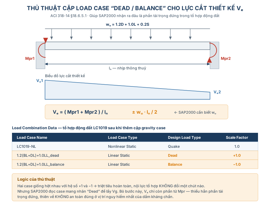
Why it works: the two cases cancel arithmetically, so the combination forces do not change at all. But SAP2000 can read the case labelled Dead and uses it as Vg when building the shear diagram from Mpr.
- The gravity factors must match that specific combination:
1.2D + 1.0L + 0.2Sfor ASCE 7-16 combination 6,0.9Dfor combination 7. - Skip this and Ve carries only the Mpr part — the entire gravity share is missing, on the unsafe side.
7. Step 3 — Design parameters
(a) Preferences
Design > Concrete Frame Design > View/Revise Preferences…| Item | Value | Note |
|---|---|---|
| Design Code | ACI 318-14 / ACI 318-19 | See section 13 on the differences |
| Multi-Response Case Design | Envelopes | |
| Consider Minimum Eccentricity | Yes | Activates M2,min = Pu(15 + 0.03h) mm, §6.6.4.5.4 |
| Seismic Design Category | Per project spec | Take it from ASCE 7; do not guess |
| Design System Rho (ρ), Sds | Per spec | Only used if SAP generates combinations itself — which we do not do |
| Phi (Shear Seismic) | 0.60 | §21.2.4.1 |
| Phi (Joint Shear) | 0.85 | §21.2.4.3 |
| Utilization Factor Limit | 0.95 | An internal threshold; keep it ≤ 1.0 |
(b) Design combinations
- Feed in the second-order set (
LC1001,LC1002…), not theL-set. - Untick
Automatically Generate Code-Based Design Load Combinations. Leave it ticked and SAP2000 generates its own linear combinations, and the entire nonlinear analysis is wasted.
(c) Overwrites
| Item | Value | Reason |
|---|---|---|
| Framing Type | Sway Special for Chapter 18 structures; Sway Ordinary otherwise | Determines the whole set of seismic checks |
| Effective Length Factor K | Program Determined | SAP takes K = 1.0, in keeping with second-order analysis |
| NonSway Moment Factor Dns | 1.0 | P-δ is already there through the segmentation |
| Sway Moment Factor Ds | 1.0 | P-Δ is already there through the nonlinear case |
8. Step 4 — Checking M<sub>2nd</sub> ≤ 1.4 M<sub>1st</sub>
This is not an optional client-requested check. ACI 318-14 §6.2.6 states that the total moment including second-order effects in compression members, restraining beams and other members shall not exceed 1.4 times the first-order moment. It is the limit on the stability sensitivity of the whole system.
Method
- 1. Run the analysis (both the
LCandL-LCsets). - 2.
Display > Show Tables > Analysis Results > Element Forces – Frames. - 3.
Select Load Cases→ take the first-order set, then the second-order set. - 4.
File > Export Current Table > To Excel, then form the ratios M3NL/M3L and M2NL/M2L.
Reading the result
- A ratio > 1.4 on members carrying appreciable moment → the structural system is too flexible. Increase sections, add walls or add bracing. No amount of “adjusting the software” will save it.
- A ratio > 1.4 where the absolute moment is near zero (say 1×10⁻⁵ against 1×10⁻⁶ kN·m) → numerical noise, safely ignored. Filter it out in Excel with a minimum-moment threshold.
- If the analysis diverges: look for instability in
Modal Analysis(an implausibly long period, a local mode shape), look for unconnected members, and re-examine the system stiffness.
9. Step 5 — Reading results and the two-pass design loop
(a) Reading straight off the 3D model
Design > Concrete Frame Design > Display Design Info…| Display | Meaning |
|---|---|
| Longitudinal Reinforcing | Beams: top/bottom As for the three zones 0–L/4, L/4–3L/4, 3L/4–L. Columns: As for the whole member |
| Rebar Percentage | Longitudinal reinforcement ratio |
| Shear Reinforcing | Av/s — stirrup area per unit length |
- Switch the display units to
Kgf, cm, Cso steel areas come out in cm² — far easier to compare against drawings than m². - Keep the column reinforcement ratio below 2%, even though ACI 318-14 §18.7.4.1 allows up to 6% (§10.6.1.1 allows 8% for ordinary columns).
- The reasons are practical: it leaves room to add steel when the 6/5 ratio fails, without changing the column section.
- Changing a column section drags beam reinforcement with it, and the HVAC/piping routing around the column — one small change ripples across the whole project.
- Above 2.5–3%, bar congestion at the joints makes construction difficult.
(b) Reading the detailed report (double-click a member → Summary)
- Beams: the
Type: Sway Speciallabel, dimensions, φ, design moments, required As and As,min, Av/s, Vp (shear from Mpr with fy × 1.25), and the torsion terms. - Columns: capacity ratio, Δns/Δs (must be 1.0 — verify it here!), K, L, shear, joint shear, and the (6/5) beam/column capacity ratio per §18.7.3.2.
- An
(Sp)label after a combination name means the result already carries a code special factor, or derives from the capacity of adjacent members — it is not raw analysis force.
(c) The two-pass loop — mandatory for seismic structures
Pass 1 gives the required As. But Ve and the 6/5 ratio must be computed from the As actually detailed, which is always larger. Stop at pass 1 and Mpr is underestimated → the design shear is too low → unsafe, and unsafe exactly where it matters most.
- Beams: enter the real As into
Reinforcement Overrides for Ductile Beams(top/bottom × left/right). - Columns: enter the real bar count, diameter and tie spacing, then switch to
Reinforcement to be Checked. - Re-run the design. Only now are Vp, joint shear and the 6/5 ratio numbers you can use.
(d) When joint shear or 6/5 reads “N/A”
SAP2000 computes these two only when six conditions are met:
- the station sits at a beam-column joint (top of column);
- the frame is a ductile moment frame;
- the column above is concrete (where one exists);
- every beam framing into the joint is concrete;
- design results already exist for the connecting members;
- the combination contains seismic load.
Miss one and you get N/A. The usual culprits: a steel beam framing into an RC column, or forgetting the Quake label in Step 2-1.
10. Step 6 — Serviceability checks
- Use the service load combinations from the project spec, not the factored ones.
- Switch the property modifiers to the service column of the table in section 4 (§6.6.3.2.2: ×1.4 but not exceeding Ig).
- Because SAP2000 cannot vary modifiers by load case, in practice you must split into two model files: one for strength, one for service. Name them clearly and record it on the calculation cover sheet, or the next reviewer will not understand why two files differ.
- Beams must satisfy the minimum depths of Table 9.3.1.1: simply supported ℓ/16, one end continuous ℓ/18.5, both ends continuous ℓ/21, cantilever ℓ/8. Satisfy the table and detailed deflection calculation is waived (§24.2, R24.2).
11. Step 7 — Remaining notes
The period used for seismic coefficients: take it from the reduced stiffness. RC structures already carry cracked regions the moment the formwork comes off (ASCE 7-10 §12.7.3(a), FEMA P-1051 §10.3.1). And it must still be capped at T ≤ CuTa per ASCE 7.
Re-check the load pattern / load case types: dead → Dead, live → Live, snow → Snow, seismic → Quake. This is the data SAP2000 uses to build the Chapter 18 shear design combinations. One wrong type on one load pattern corrupts the entire seismic branch — with no warning at all.
A response spectrum cannot run inside a nonlinear static case. If the project uses RSA rather than equivalent static forces: create a P-Delta case carrying gravity only, then define the response-spectrum case with Stiffness at End of Nonlinear Case pointing at it. P-Δ is then accounted for at the stiffness the gravity load has already softened.
Sustained load (creep): §6.7.1.2 requires the second-order analysis to account for duration of loads, shrinkage and creep. Where sustained gravity dominates a combination, the stiffness should be further divided by (1 + βdns) in the spirit of §6.6.4.4.4. Almost no software guide mentions this, but it is a code provision.
Run time: 120 nonlinear combinations means solving the system 120 times. Three ways to shorten it: Results Saved = Final State Only, fewer output stations on columns, and discarding combinations that certainly do not govern before converting.
What SAP2000 does NOT do for you: development and lap lengths, bar curtailment points, hoop detailing in plastic hinge zones (§18.6.4), transverse reinforcement within joints (§18.8.4), torsion detailing, and buildability. What SAP2000 gives you is a required steel area, not a drawing.
12. A field guide for the structural engineer
- End offsets
Automatic from Connectivity, rigid factor = 0.5 - Correct design type: beams = Beam, columns = Column; cover is to the bar centroid
- Modifiers 0.70 / 0.35 / 0.70(T) — declared at one level only, Mass & Weight = 1.0
- Torsional modifier J considered (0.1–0.2 for compatibility torsion)
- The
L-combination set copied before Convert to Nonlinear - Nonlinear cases: P-Delta, zero initial conditions, correct combination factors
Automatic Frame Mesh≥ 2 segments (not Divide Frames)- Output stations ≥ 9 on beams, including at intersections & point loads
- Seismic cases labelled
Design Load Type = Quake - The
Dead/Othergravity pair at +1 / −1 added to the seismic combinations - Design combos = the second-order set; auto-generate code-based combos unticked
- Overwrites: correct framing type, Dns = Ds = 1.0
- M2nd/M1st ≤ 1.4 (noise at moment ≈ 0 filtered out)
- Column reinforcement ratio < 2%
- Actual reinforcement entered and pass 2 run to obtain Ve, joint shear and the 6/5 ratio
- No remaining “N/A” for joint shear / 6/5 at the joints that need checking
- The serviceability file uses modifiers 1.0 / 0.5; seismic drift still uses 0.70 / 0.35
- The period used for seismic coefficients taken from the reduced-stiffness model
Supporting design tools
13. A note on ACI 318 editions
- ACI 318-19 keeps Table 6.6.3.1.1(a) and the whole Chapter 6 logic above, and adds Table 6.6.3.1.1(b) allowing a more detailed I based on the level of axial force and moment.
- The largest difference in 318-19 is in the concrete shear strength Vc (§22.5.5.1): a size-effect factor λs and the longitudinal ratio ρw now appear. Beam Av/s results will differ from 318-14, particularly for deep beams with low ρw.
- If the project spec cites 318-14, keep 318-14 in the preferences. Do not “upgrade” the code inside the software without written approval — the two sets of results will not reconcile at the review stage.
Part of the series “Structural design for industrial facilities” — Roberto Structural. The content is technical guidance; the engineer remains responsible for checking and adapting it to the conditions of each project and the requirements of the governing code.