Torsional Analysis of Structural Steel Members — Part 2: Design Procedure, Worked Examples & Code Checks
Structural Notes · No. 10·13 Aug 2026·20 min read
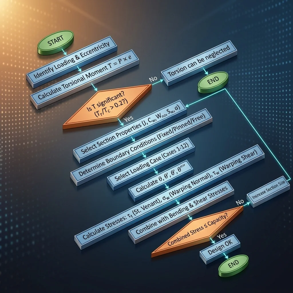
11. The seven-step design procedure
Figure 1. The torsion design procedure.
Step 1 — Establish the load and its eccentricity
Locate the point of load application on the section.
Locate the shear center — for a Channel it lies outside the web.
Compute the eccentricity e, then T = P × e (concentrated) or t = w × e (distributed).
Step 2 — Screening check: is a torsion analysis needed at all?
T_r / T_c ≤ 0.20   →   torsion may be neglected  (AISC 360 §H3.1)

Quick estimate of T_c:
  Open section  : T_c = φ · 0.6 · F_y · J / t_max
  Closed section: T_c = φ · 0.6 · F_y · C   (C from the AISC Manual)
Steps 3 to 5 — Properties, load case, derivatives
Property
Source
Note
J, Cw
AISC Manual — Dimensions & Properties
All sections
W_no
DG9 Appendix A — Table A.1
W-shape: at the flange tip
S_w
DG9 Appendix A — Table A.1
At the point being checked
Q_f, Q_w
DG9 Appendix A — Table A.1
W-shape flange and web
Compute a = √(E·Cw / G·J) and λ = L/a, pick the Case from the 12 in DG9, then evaluate four quantities at the critical location.
θ — angle of twist, used for the serviceability check.
θ' — gives the St. Venant shear stress τ_t.
θ'' — gives the warping normal stress σ_w.
θ''' — gives the warping shear stress τ_w.
Step 6 — Compute the three torsional stresses
τ_t = G · t · θ'              use the THICKEST element
σ_w = E · W_no · θ''          governs at the outer flange tip
τ_w = E · S_w · θ''' / t      usually at the flange–web junction
12. Combining stresses and checking to AISC 360
The total stress at a point is the algebraic sum of every component acting at that same point.
Total normal stress:  f_n = f_bx + f_by + σ_w + f_a
Total shear stress :  f_v = f_vx + f_vy + τ_t + τ_w

f_bx, f_by = major- and minor-axis bending   f_a  = axial
f_vx, f_vy = shear on each axis
Check
Formula
φ (LRFD)
Normal stress
f_n ≤ φ · F_y
0.90
Shear stress
f_v ≤ φ · 0.6·F_y
1.00
Von Mises
√(f_n² + 3·f_v²) ≤ φ · F_y
0.90
Closed sections (HSS) — the H3-6 interaction equation
( P_r/P_c + M_rx/M_cx + M_ry/M_cy ) + ( V_r/V_c + T_r/T_c )² ≤ 1.0

Take the LARGER of the two axes for V_r/V_c.

Nominal torsional strength:  T_n = F_cr · C
  Rectangular HSS:  C ≈ 2·(B−t)·(H−t)·t
  Round HSS      :  C = π·(D−t)²·t / 2
Ratio h/t
Limit state
F_cr
h/t ≤ 2.45·√(E/F_y)
Yielding
0.6·F_y
2.45·√(E/F_y) < h/t ≤ 3.07·√(E/F_y)
Inelastic buckling
0.6·F_y · 2.45·√(E/F_y) / (h/t)
h/t > 3.07·√(E/F_y)
Elastic buckling
0.458·π²·E / (h/t)²
Open sections — check several points
AISC 360 gives no simple interaction equation for open sections. Compute the total stress and compare with the capacity point by point — at least four points on the section.
Point
Normal stress
Shear stress
A — top flange tip
f_bx + σ_w
τ_t (small)
B — flange–web junction
f_bx
τ_t + τ_w + f_vy
C — mid-web
0
f_vy + τ_t
D — bottom flange tip
f_bx ∓ σ_w
τ_t
13. Formulas for the common loading cases
Case 1 — Pinned–Pinned, concentrated T at midspan
The most common case in practice. Boundary conditions: θ = 0 and θ'' = 0 at both ends.
Case 9 — Fixed–Free (cantilever), T at the free end
θ'(z)   =  T/(G·J) · [ 1 − cosh((L−z)/a)/cosh(L/a) ]
θ''(z)  =  T/(G·J·a) · sinh((L−z)/a)/cosh(L/a)
θ'''(z) = −T/(G·J·a²) · cosh((L−z)/a)/cosh(L/a)

Extremes:  θ and θ' peak at z = L (free end)
           θ'' and θ''' peak at z = 0 (fixed support)
14. Worked example 1 — W-shape under an eccentric load
Member        : W16×26  (A992, F_y = 50 ksi)
Span          : L = 20 ft = 240 in
Load          : P = 10 kips at midspan, eccentricity e = 6 in
End conditions: Pinned–Pinned (free warping both ends)
Design torque: T = P × e = 10 × 6 = 60 kip-in → use Case 1.
Member  : HSS 8×6×3/8  (A500 Gr.C, F_y = 50 ksi)
Span    : L = 20 ft
Load    : P = 10 kips at midspan, eccentricity e = 6 in
Also    : M_x = 50 kip-ft, V = 10 kips

T_r = P × e = 60 kip-in
B   = E · C_w · θ''            (bimoment)
σ_w = B · W_no / C_w

Bending–torsion interaction (simplified, open sections):
  M_y,Ed / M_y,Rd + σ_w,Ed / (f_y/γ_M0) ≤ 1.0
17. Design strategy and six traps
Priority order when torsion appears
1. Eliminate it — put the load through the shear center, add lateral bracing, detail connections so reactions pass through the shear center. Always the best option.
2. Minimise it — cut the eccentricity, add bracing points, use a composite slab (the concrete restrains warping of the top flange).
3. Switch to HSS — if torsion is significant and unavoidable. The calculation is far simpler because warping drops out.
4. Full open-section analysis — only when a W-shape or Channel is mandatory.
Six traps that catch engineers out
Trap
Why it bites
1. Ignoring a Channel's shear center
It lies outside the web — a load through the centroid still twists it.
2. Confusing torsional and warping restraint
A clip angle restrains twist but not warping. When unsure, assume Pinned.
3. Forgetting the twist check
Checking stress but not θ. Excessive twist causes vibration and damages cladding and glazing.
4. Missing the DG9 errata
Early printings contain formula, chart and Case-label errors. Always check the current errata.
5. Taking frame-software torque at face value
T from SAP2000/STAAD excludes warping — it is St. Venant only. You must compute σ_w and τ_w yourself.
6. Combining stresses at different points
Bending peaks at the flange, warping at the flange tip, shear in the web — you may not add extremes from different locations.
Which W-shape if you must use one?
Wide, thick flanges raise both J and Cw — clearly better.
A thick web raises J.
Greater depth raises Cw but lowers J — a trade-off.
Prefer wide-flange series (W14, W12); avoid slender sections such as W24×55 or W21×44 — their J is tiny.
18. Torsion design checklist
Does the load pass through the shear center? If so, there is no torsion.
Compute T = P × e using a correctly located shear center.
Check T_r/T_c ≤ 0.20 — if satisfied, stop; torsion is negligible.
Choose the section type: HSS if torsion is significant.
Look up J, Cw, W_no, S_w from the AISC Manual and DG9 Appendix A.
Compute a = √(E·Cw / G·J) and L/a.
Determine the end conditions: Fixed, Pinned or Free.
Select the load Case from the 12 in DG9 Appendix B.
Evaluate θ, θ', θ'', θ''' at the critical location.
Compute τ_t, σ_w and τ_w.
Combine f_n and f_v at no fewer than four points on the section.
Check f_n ≤ φ·F_y and f_v ≤ φ·0.6·F_y.
Check the twist θ against the serviceability limit.
For HSS: check equation H3-6 ≤ 1.0.
19. Quick reference tables
MATERIAL CONSTANTS (steel)
  E = 29,000 ksi = 200,000 MPa
  G = 11,200 ksi =  77,200 MPa
  ν = 0.30

LRFD LIMITS
  Normal stress : f_n ≤ 0.90 · F_y
  Shear stress  : f_v ≤ 1.00 · 0.6·F_y
  Von Mises     : √(f_n² + 3f_v²) ≤ 0.90 · F_y
J, Cw and a for common W-shapes
Section
J (in⁴)
Cw (in⁶)
W_no (in²)
a (in)
W8×31
0.536
212
12.2
32.0
W10×49
1.39
620
16.5
34.0
W12×50
1.71
1,880
25.0
53.3
W14×48
1.45
2,240
27.2
63.2
W14×90
4.06
4,990
33.0
56.4
W16×26
0.262
456
15.5
67.1
W16×50
1.52
2,340
23.6
63.1
W21×44
0.770
2,110
24.5
84.2
W24×55
1.18
3,870
29.1
92.0
Channels and HSS
Section
J (in⁴)
Cw (in⁶) / C (in³)
Note
C10×15.3
0.209
54.8
e₀ = 0.634 in
C15×33.9
0.904
349
e₀ = 0.788 in
HSS 8×6×3/8
86.2
C = 72.7
Common
HSS 12×8×1/2
353
C = 265
Very strong
20. Seven key recommendations
Try to detail the torsion away before you start calculating.
If torsion is significant, use a closed section (HSS) — simpler and far more effective.
Locate the shear center precisely, especially for Channels.
Get the end conditions right — Fixed versus Pinned changes the answer dramatically.
Always check the twist θ alongside the stresses.
Combine stresses at the same point — never add extremes from different locations.
Check the DG9 errata before trusting any formula.
Part of the “Industrial structural design guide” series by Roberto Structural. The content is technical guidance only; the engineer remains responsible for verifying and adapting it to each project and the governing code. Codes change — always check the current edition, including the AISC Design Guide 9 errata.
 Roberto