 Roberto
7. SMF — the six-step procedure
The special moment frame is the most ductile system and the most demanding to detail: R = 8 gives the smallest design forces, but in exchange the connections must survive 0.04 rad of drift — very large inelastic deformation.
Step 1 — Choose the beam section
- Strong enough for the seismic combination — but drift usually governs, not strength.
- Flange bf/2tf ≤ 0.32·√(E/Fy) and web h/tw ≤ 2.57·√(E/Fy) — the λhd limits.
- Zbf ≥ 0.7 × Zb — the flanges must carry enough of the bending capacity, ruling out sections with an oversized web.
LATERAL BRACING for SMF beams
  Maximum spacing:  Lb ≤ 0.095 × ry × E / Fy
  A brace is required at every expected plastic hinge
  Brace BOTH flanges, top and bottom
  Brace force ≥ 2% of the flange strength   (6% near an RBS)
Step 2 — Choose the column section
- FEMA 350 prequalification covers W12 and W14 only.
- b/t ≤ λhd when ΣM*pc/ΣM*pb < 2.0; otherwise λmd applies.
Amplified axial combination for columns:
  Pu = 1.0D + 0.5L + Ω₀ × QE      (compression)
  Pu = 0.9D − Ω₀ × QE             (tension)

Need not exceed the force delivered by 1.25 × the ultimate
capacity of the adjoining beams or braces.

EXCEPTION: if fa < 0.3·Fy under the seismic combination,
the amplified axial check is not required.
Step 3 — The strong column – weak beam check
ΣM*pc / ΣM*pb  ≥  1.0

COLUMN:  M*pc = Zc × (Fyc − Puc/Ag)
          Zc  = column plastic modulus
          Puc = column axial load under the seismic combination
          Sum the column above and below the joint

BEAM:    M*pb = Mpr + Vp × sh
          Mpr = Cpr × Ry × Fy × Ze
          Vp  = shear at the hinge (gravity + 2·Mpr/L')
          sh  = distance from column face to the hinge
Sum the left and right beams at the jointStep 4 — Design the panel zone
The panel zone is the column web right at the joint. When the beams either side carry opposing moments this zone takes a very large shear — easy to overlook because it is not a separate member.
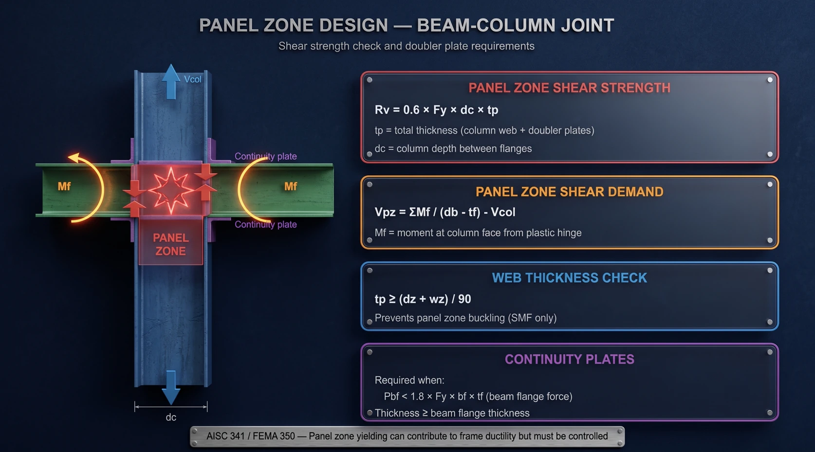
Panel zone shear:
  Vpz = ΣMf / (db − tbf) − Vcol

Shear strength (AISC 360 §J10.6):
  φRn = 0.60 × Fy × dc × tp × [ 1 + 3·bcf·tcf² / (db·dc·tp) ]

  tp = total column web thickness plus doubler plate
  dc = column depth between flanges
  bcf, tcf = column flange width and thickness

Web buckling check (SMF only):
  tp ≥ (dz + wz) / 90
Steps 5 and 6 — Continuity plates and column splices
- Continuity plates are needed when the concentrated flange force exceeds the column flange capacity — specifically when Pbf > 1.8 × Fy × bf,col × tf,col.
- For SMF the plate must be at least as thick as the beam flange. CJP weld to the column flange, fillet weld to the web, across the full flange width.
- Column splices go in the middle third of the storey, at least 1.0 m above the beam. They must resist tension from overturning, match the shear capacity of the column above, and provide at least 50% of its flexural capacity.
8. Seismic beam-to-column connections
After Northridge, FEMA 350 and AISC 358 established a set of prequalified connections — types already tested, so they may be used without further testing. This is the single biggest practical change.
| Connection | Code | Systems | Character |
|---|---|---|---|
| Welded flange – bolted web | WUF-B | OMF | Simplest |
| Welded flange – welded web | WUF-W | OMF, SMF | Fully welded |
| Reduced beam section | RBS | OMF, SMF | Most common |
| Bolted unstiffened end plate | BUEP | OMF, SMF | Thin end plate |
| Bolted stiffened end plate | BSEP | OMF, SMF | For deeper beams |
| Bolted flange plates | BFP | OMF, SMF | Bolted plates |
| Welded flange plate | WFP | OMF, SMF | Added flange plate |
RBS — the most common type, in six steps
The principle is blunt: cut away part of the beam flange near the column so the local capacity drops and the plastic hinge forms in the cut zone instead of at the column face. This is the main Northridge lesson made physical.
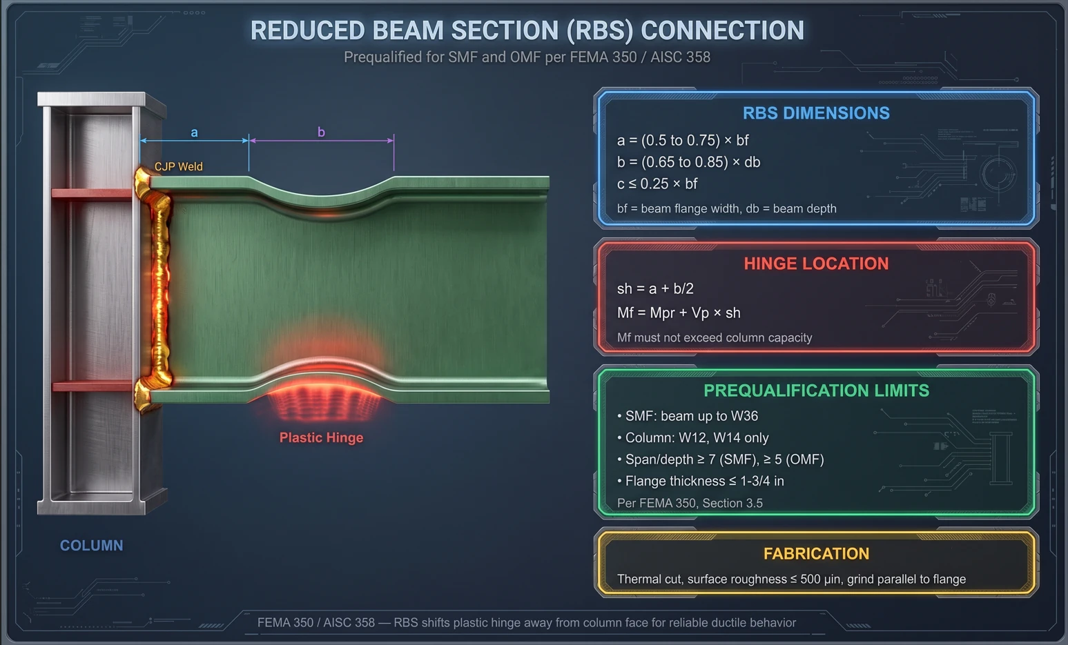
1. Cut geometry
     a = (0.50 ~ 0.75) × bf      column face to start of the cut
     b = (0.65 ~ 0.85) × db      length of the cut
     c ≤ 0.25 × bf               depth of cut each side

2. Plastic modulus at the reduced zone
     ZRBS = Zb − 2 × c × tbf × (db − tbf)

3. Plastic hinge moment
     Mpr = Cpr × Ry × Fy × ZRBS        with Cpr = 1.1

4. Shear at the hinge
     Vp = 2·Mpr / L' + Vgravity        L' = L − 2·sh

5. Moment at the column face
     Mf = Mpr + Vp × sh                sh = a + b/2

6. Checks
     Mf ≤ φd × Ry × Fy × Zb     (no yielding at the column face)
     Strong column – weak beam, using M*pb = Mf
Panel zone, using Mf| Prequalification limit | SMF | OMF |
|---|---|---|
| Maximum beam depth | W36 | W36 |
| Maximum flange thickness | 44 mm | 44 mm |
| Column | W12, W14 | Unrestricted |
| Minimum span-to-depth | 7 | 5 |
End plate connections — a good fit for pipe racks
- BUEP, 4 bolts unstiffened: beams up to W30 for OMF, W24 for SMF. A36 end plate, pretensioned A325 or A490 bolts.
- BSEP, 8 bolts stiffened: for deeper beams, with stiffeners at both flanges and a thicker end plate.
- Hinge location: sh = dc/2 + tpl + db/3.
9. SCBF — designing the gusset plate
In a concentrically braced frame the tension brace yields while the compression brace buckles — both dissipate energy. Once buckled, the compression brace sheds load and forces redistribute.
| Brace parameter | Requirement |
|---|---|
| Slenderness KL/r | ≤ 200 |
| b/t flange and web | ≤ λhd |
| K out-of-plane | 1.0 |
| K in-plane | 0.65 |
| Tension share | 30% to 70% of the storey shear |
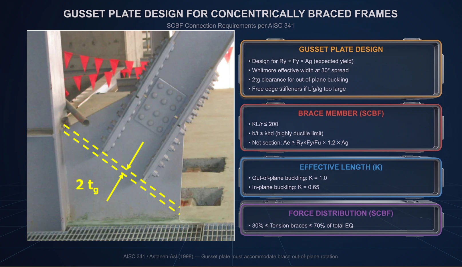
The gusset plate is the most critical element in a braced connection. Get it wrong and the system loses its seismic capacity no matter how correct the braces are.
PRINCIPLE 1 — Design for the EXPECTED brace strength
  Pu = Ry × Fy × Ag

PRINCIPLE 2 — Whitmore section
  30° spread from each side of the connection
  Lw = 2 × Lconn × tan(30°) + wbrace

PRINCIPLE 3 — The 2tg offset  (characteristic of SCBF)
  Keep the brace end at least 2 × tg clear of the gusset edge.
  This clearance lets the gusset FLEX when the brace buckles
  out of plane. Without it the gusset fractures in a brittle way.

PRINCIPLE 4 — Free-edge stiffening  (Astaneh-Asl 1998)
  Lfg = 0.75 × tg × √(E / Fy)
  A free edge longer than this needs a welded stiffener.

PRINCIPLE 5 — Net section (bolted connections)
Ae ≥ (Ry × Fy / Fu) × 1.2 × AgV and inverted-V configurations — extra rules
- The beam must be continuous between columns, not spliced at the brace intersection.
- The beam must carry D + L with the braces removed — that is, assuming the braces have failed.
- Check the unbalanced force: the tension brace yields at Ry·Fy·Ag while the compression brace retains only 0.3·Pn — the difference loads the beam.
- Brace both flanges of the beam at the intersection, with a brace force of at least 2% of the flange strength.
10. EBF — designing the link beam
The EBF combines both families: the braces give the stiffness of a braced frame while the link gives the ductility of a moment frame. The link is engineered as a controlled fuse.
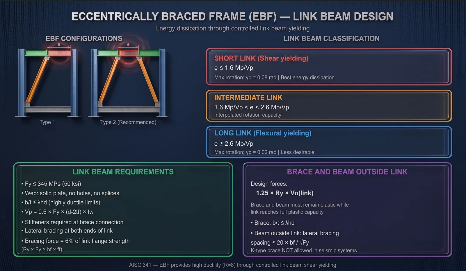
STEP 1 — Link length
  Vp = 0.6 × Fy × (d − 2tf) × tw
  Mp = Fy × Zx

  Shear link (best) :  e ≤ 1.6 × Mp/Vp      γp = 0.08 rad
  Intermediate      :  1.6 < e·Vp/Mp < 2.6   interpolate
  Flexural (weakest):  e ≥ 2.6 × Mp/Vp      γp = 0.02 rad

STEP 2 — Link section
  Material Fy ≤ 345 MPa
  The web must be a SOLID plate: no doubler, no holes, no splice
  Flange and web b/t ≤ λhd

STEP 3 — Link rotation
  γp = (L/e) × θ        θ = Cd × θe / Ie
Step 4 — Link stiffeners
- Full-depth web stiffeners at both ends of the link where the braces frame in.
- Intermediate stiffeners for a shear link (e ≤ 1.6·Mp/Vp): spacing ≤ 30·tw − d/5.
- For 1.6 < e·Vp/Mp ≤ 2.6: spacing ≤ 52·tw − d/5.
- For e > 2.6·Mp/Vp: intermediate stiffeners are not required.
- Stiffener thickness ≥ 10 mm or tw, whichever is greater.
BRACE AND BEAM OUTSIDE THE LINK — protected elements
  Design force = 1.25 × Ry × Vn(link)

  Brace        : b/t ≤ λhd
Outer beam : lateral bracing at ≤ 20·bf/√Fy| EBF configuration | Assessment |
|---|---|
| D-brace — one brace, link at the end | Simple, undemanding on the beam-column connection |
| V-brace — two braces, link at mid-span | Recommended — the best balance |
| K-brace | PROHIBITED in EBF |
11. OMF — when it is enough
OMF applies in SDC A, B and C. R = 3.5 means larger design forces than an SMF, but in exchange the detailing is far simpler. For most industrial buildings in low-seismicity zones this is the sensible choice.
| Requirement | SMF | OMF |
|---|---|---|
| Strong column – weak beam | Required | Not required |
| b/t limit | λhd | λp (compact) |
| Lateral bracing | 0.095·ry·E/Fy | 0.17·ry·E/Fy |
| Connection | Prequalified per AISC 358 | Only needs to reach 0.02 rad |
| Panel zone buckling | Must be checked | Not required |
| Column splice | CJP, 50% Mpn | Simpler |
Design moment at the connection:
  Mf = min( 1.1 × Ry × Mp ,  moment from the amplified combination )

Design shear:
  Vu = min( 2 × 1.1 × Ry × Mp / Ln + V(1.2D+0.5L) ,
Vu from the amplified combination )12. Applying this in Vietnam
- Most industrial steelwork in Vietnam has not been designed for seismic action properly.
- TCVN 9386:2012 is not yet widely applied to steel structures.
- Foreign-invested projects demand AISC/ASCE while local experience with seismic detailing is still thin.
- Capacity design and prequalified connections remain very new concepts here.
| Zone | agR (g) | Estimated SDC | Recommended system |
|---|---|---|---|
| Very low | < 0.04 | A | No special seismic design |
| Low | 0.04 – 0.08 | B | OMF or OCBF |
| Moderate | 0.08 – 0.12 | C | IMF, SCBF or EBF |
| High | > 0.12 | D | SMF, SCBF, EBF, BRBF |
Recommendations by building type
| Building type | System and connection |
|---|---|
| Single or two-storey plant | OMF or OCBF suffices in most zones. BUEP or WUF-B connections. Simple and economical detailing. |
| Pipe rack / modular structure | Open frames with no rigid diaphragm. OCBF is most common, with end-plate connections. Note: an OMF pipe rack is very hard to brace laterally, so consider SCBF. |
| Steel buildings above 5 storeys | Above agR = 0.08g an IMF or SMF is required. Consider a dual system (SMF + SCBF) for both stiffness and ductility. RBS connections are recommended for SMF. |
| Cold-formed steel | AISC 341 does not apply. Use AISI S400 instead. |
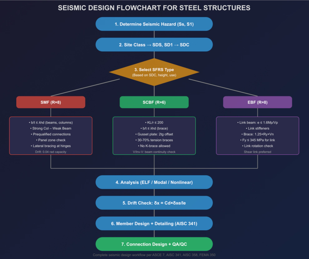
13. Seismic design checklist
- Establish Ss, S1 (or agR) from USGS / TCVN maps — ASCE 7 Ch.11.
- Classify the site, Site Class A–F — ASCE 7 Ch.20.
- Compute SDS, SD1 and determine the SDC — ASCE 7 Ch.11.
- Select the SFRS with its R, Ω₀, Cd — ASCE 7 Table 12.2-1.
- Compute base shear V = Cs × W — ASCE 7 §12.8.
- Analyse by ELF or modal methods — ASCE 7 §12.8–12.9.
- Check drift δx = Cd × δxe / Ie — ASCE 7 §12.12.
- Choose sections meeting b/t ≤ λhd / λmd / λp — AISC 341 Table D1.1.
- Verify strong column – weak beam, ΣM*pc ≥ ΣM*pb — AISC 341 §E3.4a.
- Compute Mpr = Cpr × Ry × Fy × Ze — AISC 341 / FEMA 350.
- Check the panel zone, φRn ≥ Vpz — AISC 360 §J10.6.
- Detail the continuity plates — AISC 341 §E3.6f.
- Select a prequalified connection — AISC 358; detail it per FEMA 350 Ch.3.
- Design the column splice: CJP welds, correct location, adequate strength — AISC 341 §D2.5.
- For CBF: check the gusset — 2tg offset, Whitmore, Lfg — AISC 341 §F2.
- For EBF: check the link — e, γp, stiffeners — AISC 341 §F3.
- Mark the protected zones and attach nothing to them — AISC 341 §I2.
- Demand-critical welds meet the CVN requirement — AISC 341 §A3.4.
- Put a QA/QC plan in place for weld and bolt inspection — FEMA 353.
14. Three things worth keeping
Seismic design is not merely computing forces and checking sections. It is a philosophy: choose in advance where damage is permitted, then protect everything else.
- Capacity design — always make the protected element stronger than the expected strength of the fuse, not its nominal value.
- Detailing decides the outcome — connections, welds and gusset plates determine whether the structure behaves as designed. Northridge failed in the details, not in the analysis.
- Appropriate beats maximal — an SMF is not always needed. In low-seismicity regions like most of Vietnam, an OMF or OCBF is both safe and economical.
References: FEMA 350 · AISC 341-22 · ASCE 7-22 · AISC 358-22 · TCVN 9386:2012 · Astaneh-Asl (1998) Seismic Behavior and Design of Gusset Plates. Part of the “Industrial structural design guide” series by Roberto Structural. The content is technical guidance only; the engineer remains responsible for verifying and adapting it to each project and the governing code.