 Roberto
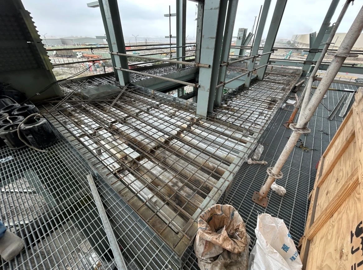
1. What is a deck slab?
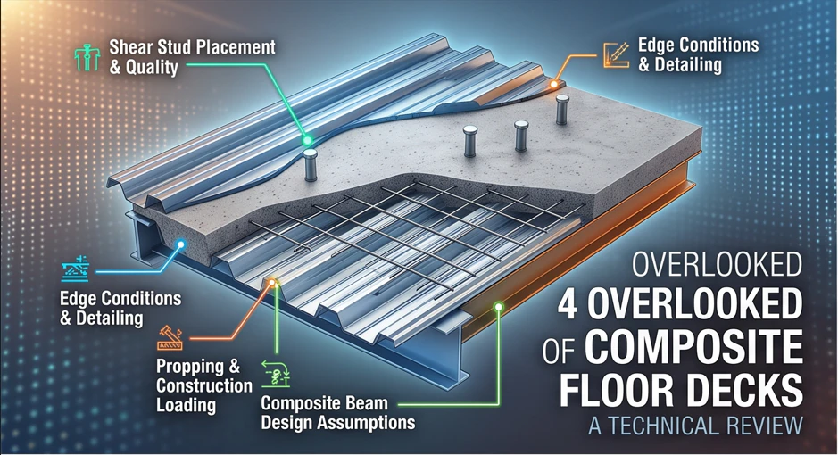
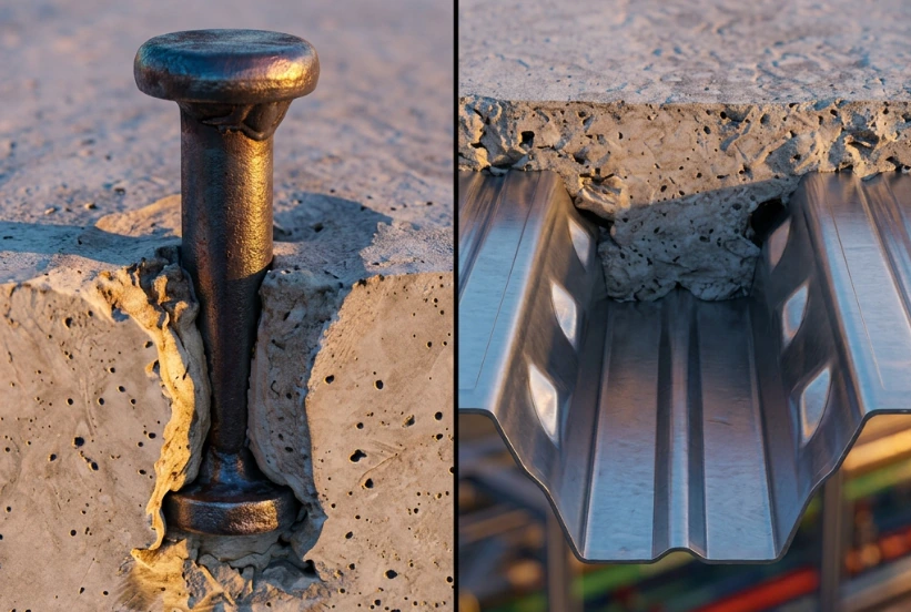
A deck slab uses profiled steel sheeting as permanent formwork with concrete cast on top. Two families differ fundamentally:
- Composite deck: embossed sheeting mechanically interlocked with the concrete — the sheeting is the tensile reinforcement.
- Form deck: sheeting acts as formwork only; reinforcement is placed separately.
Advantages on steel-framed buildings:
- Shoring eliminated or minimised; the sheeting becomes a safe working platform immediately after installation.
- Erection speed matches the steel programme; hollow ribs reduce self-weight against a solid slab of equal span and provide ready-made routing for conduits and cables.
2. Modelling in analysis software
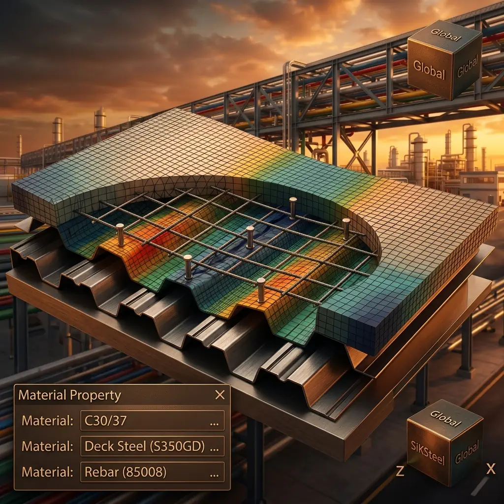
The three area-section types supply three different behaviours:
- Plate: out-of-plane bending and shear.
- Membrane: in-plane axial (f11, f22, f12).
- Shell: both Plate and Membrane combined.
For Shell and Plate only, the software further distinguishes how transverse shear is treated:
- Thin: transverse shear deformation ignored — use where t/L (short span) < 1/10–1/20.
- Thick: transverse shear included — use where t/L > 1/5–1/10.
This option does not apply to Membrane.
An often-missed point: a 200 mm slab does not contain 200 mm of solid concrete — the ribs are voided, and in-plane stiffness comes only from the topping above the rib crest. Deck is orthotropic: stiffness parallel to the ribs is markedly lower than perpendicular to them, so f11 ≠ f22.
On diaphragms, the essential distinction:
- Rigid is a kinematic constraint that works independently of shell stiffness. It remains effective even with Stiffness Modifiers = 0 or Section Properties = None.
- Semi-rigid is the opposite, behaviour relies entirely on the shell's real membrane stiffness (f11, f22, f12). It takes effect only where Section Type = Shell or Membrane with Stiffness Modifiers > 0.
Semi-rigid becomes meaningless where Section Type = Plate, or Properties = None, or Stiffness Modifiers = 0: there is no lateral load path, and the 5% accidental eccentricity requirement is not genuinely enforced.
3. Two ways to support equipment
Via an RC pedestal on the slab (anchor bolts or embedded plate cast into the pedestal): the load enters the slab. Deck slabs have a thin effective depth and are punching-shear governed, so this route suits small to medium supports — pipe supports, pump and compressor bases. Installation must wait for the pedestal to gain strength, which constrains the erection sequence.
Directly to the steel beam below, penetrating the slab: the load bypasses the slab and enters a member actually designed to carry it. This is the route for heavy equipment — vertical and horizontal vessels, items with significant horizontal reactions. The trade-off: it must be erected before the concrete pour, and it needs dedicated joint detailing — trimming bars around the opening, plus waterproofing and movement provision at the interface.
Comparison
| With RC Pedestal | Without RC Pedestal | Remark | |
|---|---|---|---|
| Structural characteristic | Slab support | Structural support | |
| Load transfer | Limited | Less restricted | |
| Erection sequence | After pedestal grouting | Before slab pour | Special joint consideration; without pedestal, no sequence restriction |
Applicability
| With RC Pedestal | Without RC Pedestal | Remark | |
|---|---|---|---|
| Vertical equipment | ✗ | ✓ | |
| Horizontal equipment | ✗ | ✓ | |
| Pump & compressor | ✓ | ✗ | Frame-type compressor not applicable |
| Steel structure | ✓ small supports ✗ large supports | ✓ | |
| Pipe support | ✓ small supports ✗ large supports | – |
The pump & compressor appears to contradict the “heavy loads go straight to the beam” principle. The reason is not load magnitude but vibration: a concrete pedestal provides mass and damping to absorb rotating-machine excitation, whereas a direct rigid connection would feed that vibration into the steel frame.
4. Construction stage and temporary bracing
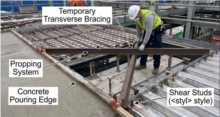
Before the concrete gains strength, the diaphragm does not yet exist. This is the most commonly missed point, and it removes two things at once:
- The lateral load path: the slab has no in-plane stiffness to distribute lateral load back to the primary system.
- Lateral restraint to the beams: the compression flange loses its bracing, and beam capacity becomes governed by lateral-torsional buckling rather than the plastic moment.
Engineers need to take into account the non-working state of the slab during this phase. Designing a temporary or permanent horizontal bracing system is necessary.
Closing
Deck slabs look simple, but most errors do not lie in thickness or concrete grade — they lie in modelling assumptions and in the load path. All four points above stem from a single question: where does this force actually go?
Part of the series "Structural design for industrial facilities" — Roberto Structural. The content is technical guidance; the engineer remains responsible for checking and adapting it to the conditions of each project and the requirements of the governing code.